Mery Explosive Engine
The picture above is NOT my engine. I can only hope mine turns out half as nice. That picture came from the Martin Model & Pattern Website. I'll replace it once mine gets to a more presentable state.
I bought my castings (Kit #314) from Gary Martin at Cabin Fever Expo 2011. I've seen a few of these engines and have always been intrigued by them so I decided to take the challenge. Gary has a good set of prints that are included with the kit. The prints are just that, prints. Don't expect instructions which is what makes this a kit for experienced builders. That's not a knock on Gary, it's the way it would be working in a shop professionally. With this page I'm not nessesarily trying to make instructions but maybe help with some of the chalenging stages of the build. There are a few other great Mery build sites out there, I'm going to add my build experience to the community. Like the old saying goes, there's more than one way to skin a cat, this site is to show how I went about it. The pictures I'm posting are high resolution so you should be able to see some of the finer details, but if you're on a slow connection they might take a second or so to load. Also, the picture's filename is the date in the format YearMonthDay.
I had taken some pictures of the initial layout process but shortly after that, my phone with the camera decided to reset itself to factory default and I didn't have the pictures copied to the computer. Oh well. Keep in mind, before you do anything on a casting, you need to find out where in the casting, the finished part is hiding. To do that, you need to layout everything and scribe the layout lines. For the most part, finding the centers and scribing them will get what you need. While you look through my pictures, you'll see a lot of the layout lines.
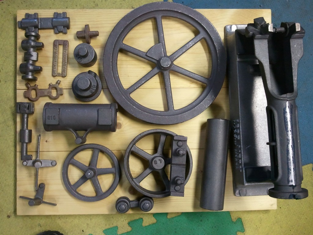 Here
is a shot of the castings pretty much as I bought them. In
them somewhere is hiding a Mery Explosive Engine. In the
following pages I'll document my journey.
Here
is a shot of the castings pretty much as I bought them. In
them somewhere is hiding a Mery Explosive Engine. In the
following pages I'll document my journey.
These first four are the very first cuts on the base. I had
to establish a starting point. Before I cut these, I layed out
the center of the bore on the granite plate using a height gauge.
Gary leaves 3 raised pads on the top of the casting and machines
them to 1.500" above the centerline of the bore. Knowing that,
I could find the rest of the dimensions from that plane. For instance, laying it
on those pads, I scribed the center of the bore EVERYWHERE I could
reach with the height gauge. I'll use this as the primary reference
line for almost everything. This is important because you may
not always be able to get to all of the marks or you may cut away a
mark so the more scribe markings you make, the better.
Sometimes you may not be able to get back to that layout setup after
cutting so make sure you do a thorough job. Notice the support
under the front pedestal. I used T nuts and threaded rod with
some rubber to dampen out the vibration. It's clamped on the
table sitting on those 3 pads. I'm only cutting the bottom of
the stand in this setup but I'll use this as my datum plane.
 NOTE: I didn't find out until too late that the pads I refered to
above were not quite right. The single pad on the bore end was
right but the pair on the crank end were about 1/16 too high and it
threw off the 45deg crank shaft pads and hole. I caught it in
time to adjust but it almost caused me to mill the 45deg pads too
thin. I should have caught this in the layout stage.
NOTE: I didn't find out until too late that the pads I refered to
above were not quite right. The single pad on the bore end was
right but the pair on the crank end were about 1/16 too high and it
threw off the 45deg crank shaft pads and hole. I caught it in
time to adjust but it almost caused me to mill the 45deg pads too
thin. I should have caught this in the layout stage.
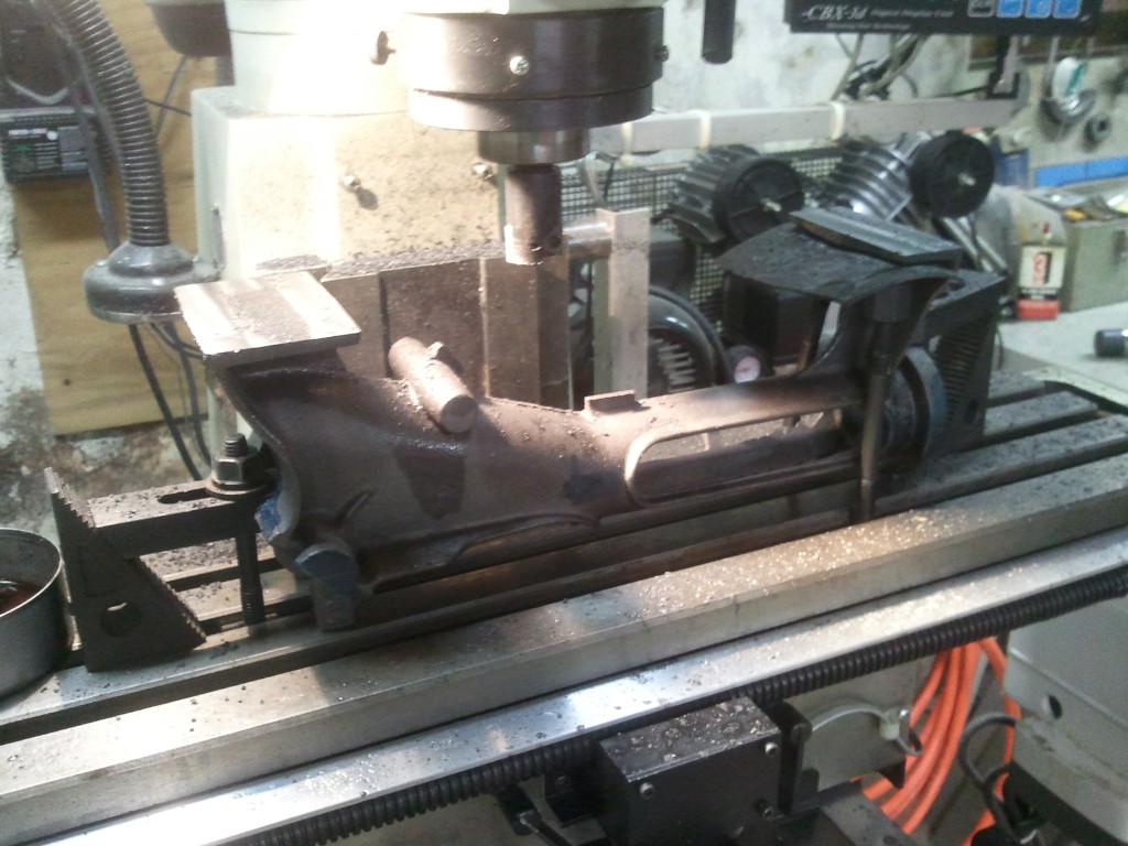
This set shows boring the base. After cutting the pedestal
bases shown above, I clamped the base to angle plates like this on the granite
plate. I found the center of the bore and back end of the base
and scribed a layout line all around. Now I have both the X
and Y centers of the casting. Z axis (length) I'm not
concerned with yet.
I used the angle plates because my table
wasn't wide enough to get the front and back legs on it. Plus
this gave me a bit of portability for the next cuts. I'm using
a Shop Task mill / lathe to bore this. The secret to boring this
is getting everything ROCK solid or you'll start chatter that will
be next to impossible to get out. All those flimsy looking
clamps are more or less vibration dampening. It all adds up.
You have to be careful though not to cause a warp or bow in the
casting while clamping it.
 Indicating the base to parallel with the lathe.
 The small boring bar chattered so I swapped it out for a bigger one.
It helped a little. I found the bore center using the layout
lines.
The small boring bar chattered so I swapped it out for a bigger one.
It helped a little. I found the bore center using the layout
lines.
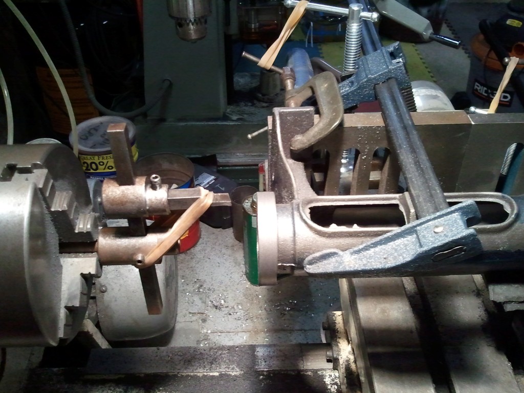 Cutting the outside of the flange face. I used a circle cutter
with a lathe bit. The rubber bands take the ringing chatter
out of the cutter. It's not the most solid setup but it worked
for this application.
Cutting the outside of the flange face. I used a circle cutter
with a lathe bit. The rubber bands take the ringing chatter
out of the cutter. It's not the most solid setup but it worked
for this application.
 While I had the base setup on the angle plates, I took a few cleanup cuts just to get a
machined face parallel to the bore. I could always just
indicate the bore but these will be way easier for future setups.
While I had the base setup on the angle plates, I took a few cleanup cuts just to get a
machined face parallel to the bore. I could always just
indicate the bore but these will be way easier for future setups.
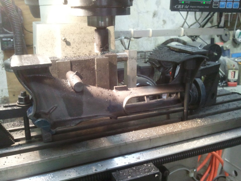
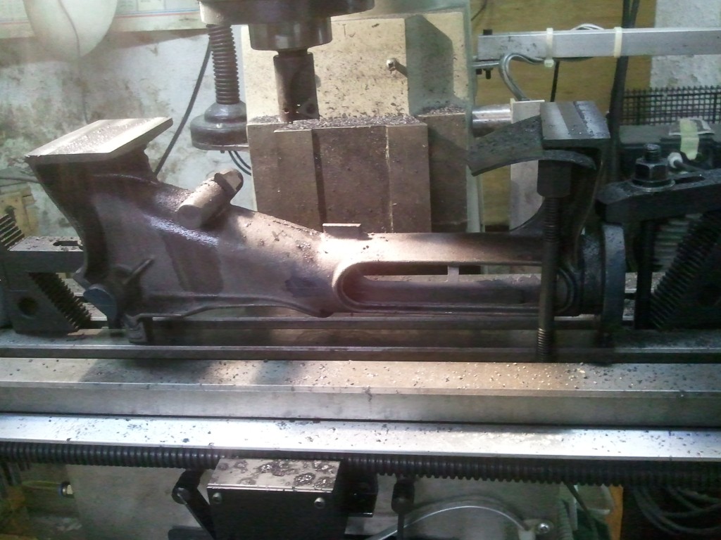
 Now to cut the pads for the main bearings. Note the stops in
the table slots. The piece is pulled up against them to hold
parallel to the bore. These are what I took a very light cut
on in the shot above for just this reason. This is also where the
error became apparent with the setup pads I mentioned above.
Now to cut the pads for the main bearings. Note the stops in
the table slots. The piece is pulled up against them to hold
parallel to the bore. These are what I took a very light cut
on in the shot above for just this reason. This is also where the
error became apparent with the setup pads I mentioned above.
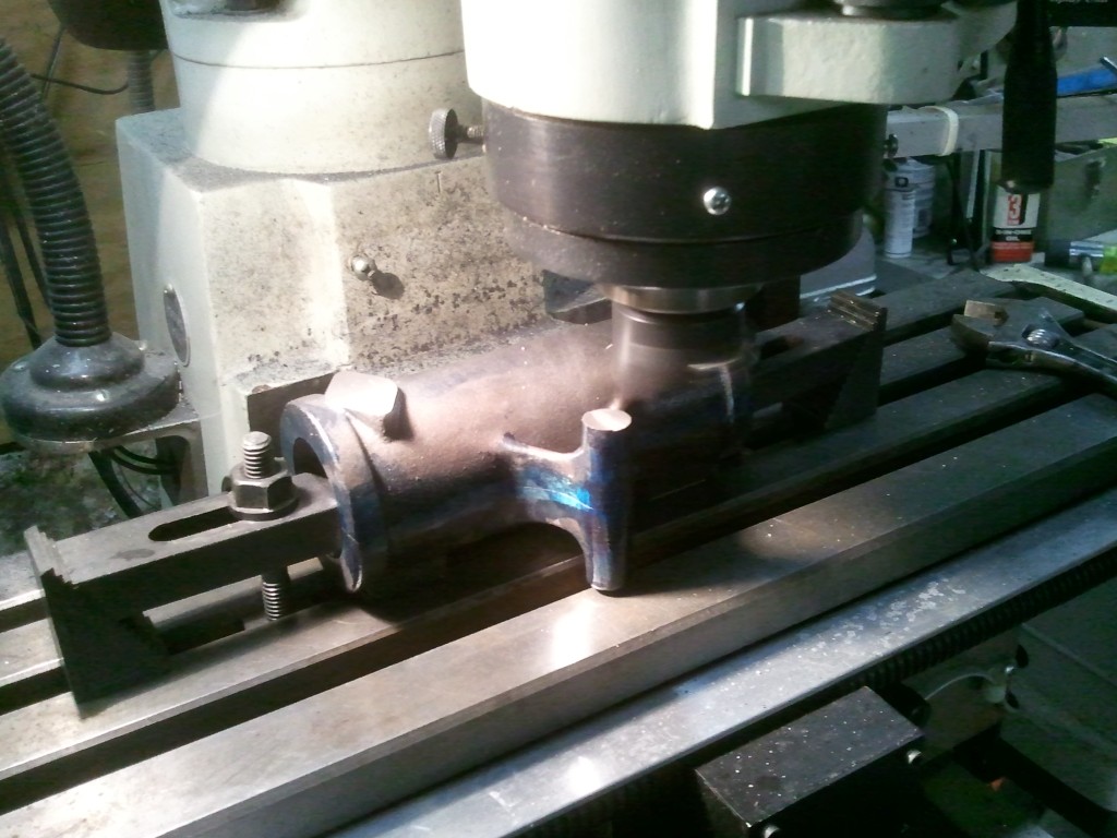
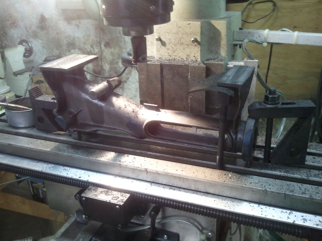
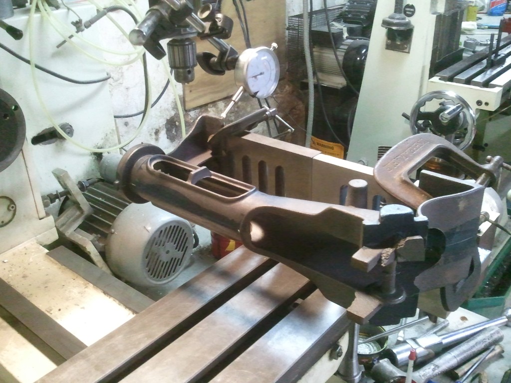
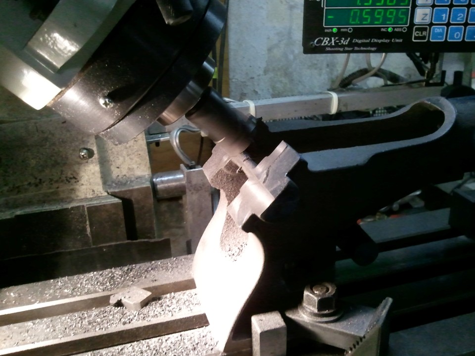
 I
took a skim cut on the exhaust side of the cylinder while clamping on
the intake side. I then flipped it over and using some shim
stock to bring things better into level with the scribed centers, I
took another skim cut on the intake side. Flip again to cut to
finish exhaust from bore center then back to finish intake.
I
took a skim cut on the exhaust side of the cylinder while clamping on
the intake side. I then flipped it over and using some shim
stock to bring things better into level with the scribed centers, I
took another skim cut on the intake side. Flip again to cut to
finish exhaust from bore center then back to finish intake.
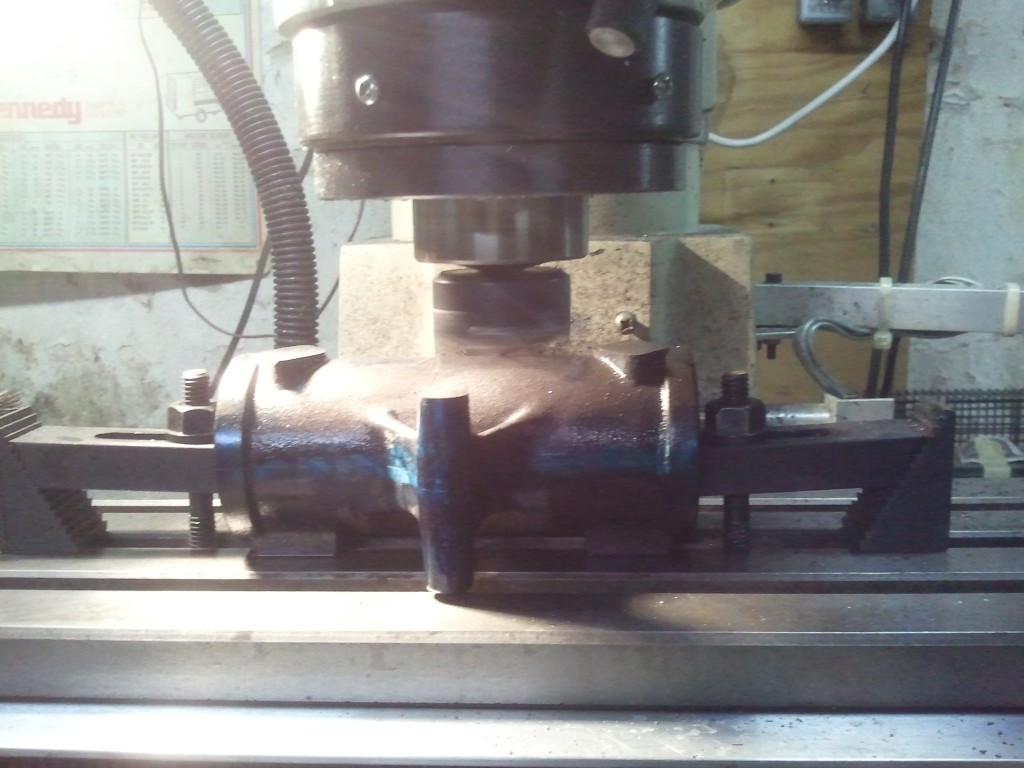
 I'm not sure if these are with or without the liner. I was so
wrapped up in the work that I forgot the camera. Either way,
the exhaust and intake pads are finished. I used them to
locate center of the bore but remember, those pads are different
distances from the center.
I'm not sure if these are with or without the liner. I was so
wrapped up in the work that I forgot the camera. Either way,
the exhaust and intake pads are finished. I used them to
locate center of the bore but remember, those pads are different
distances from the center.
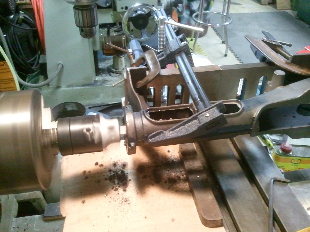
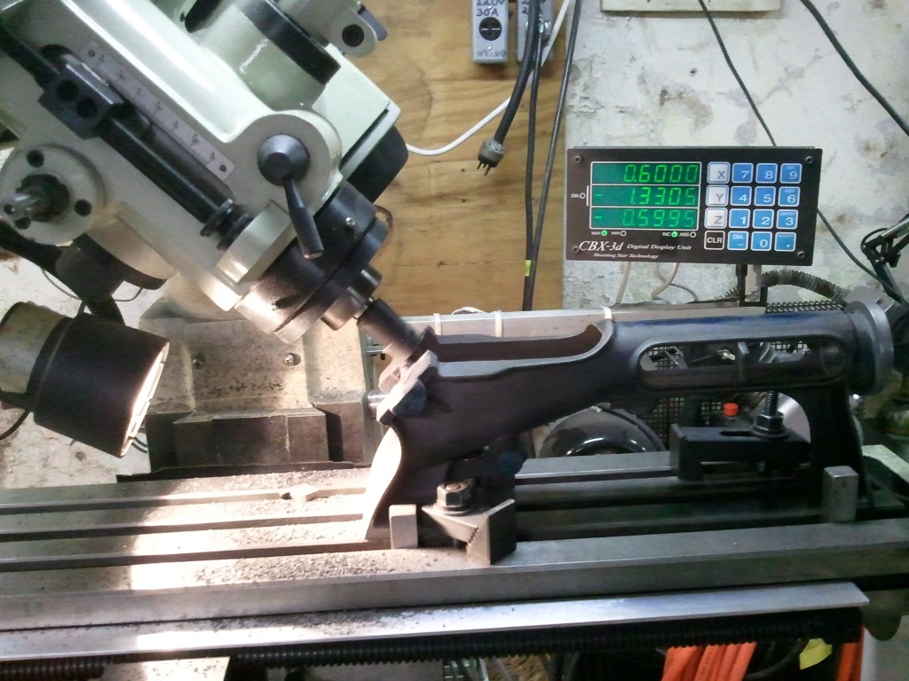
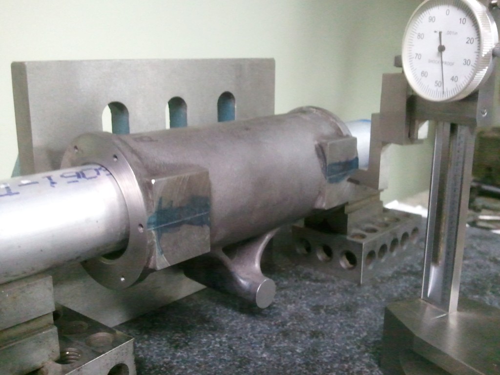
 The
setup here is about a simple as it gets. Stand it on end and
indicate the bore to center. Then get out your Machinist
Handbook and find the section about jig boring bolt circles. Don't
forget, the head end and body end are different bolt circle
diameters! Blind tapping 5-40 holes in cast iron is good for
the nerves.
The
setup here is about a simple as it gets. Stand it on end and
indicate the bore to center. Then get out your Machinist
Handbook and find the section about jig boring bolt circles. Don't
forget, the head end and body end are different bolt circle
diameters! Blind tapping 5-40 holes in cast iron is good for
the nerves.
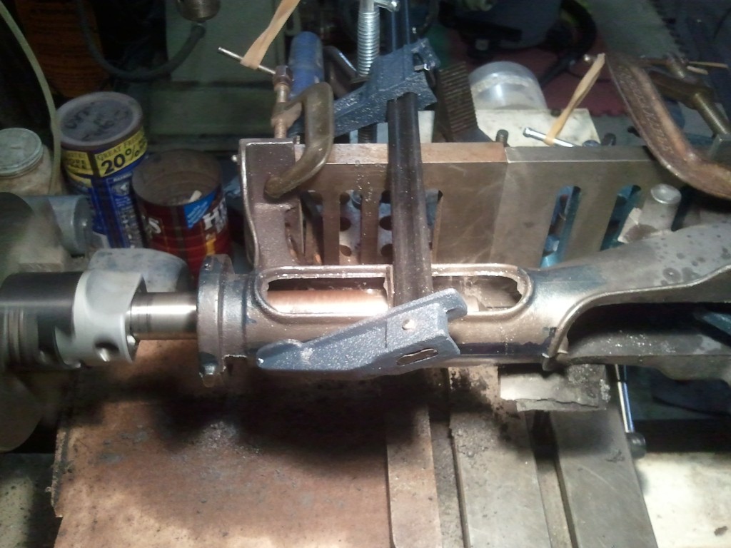
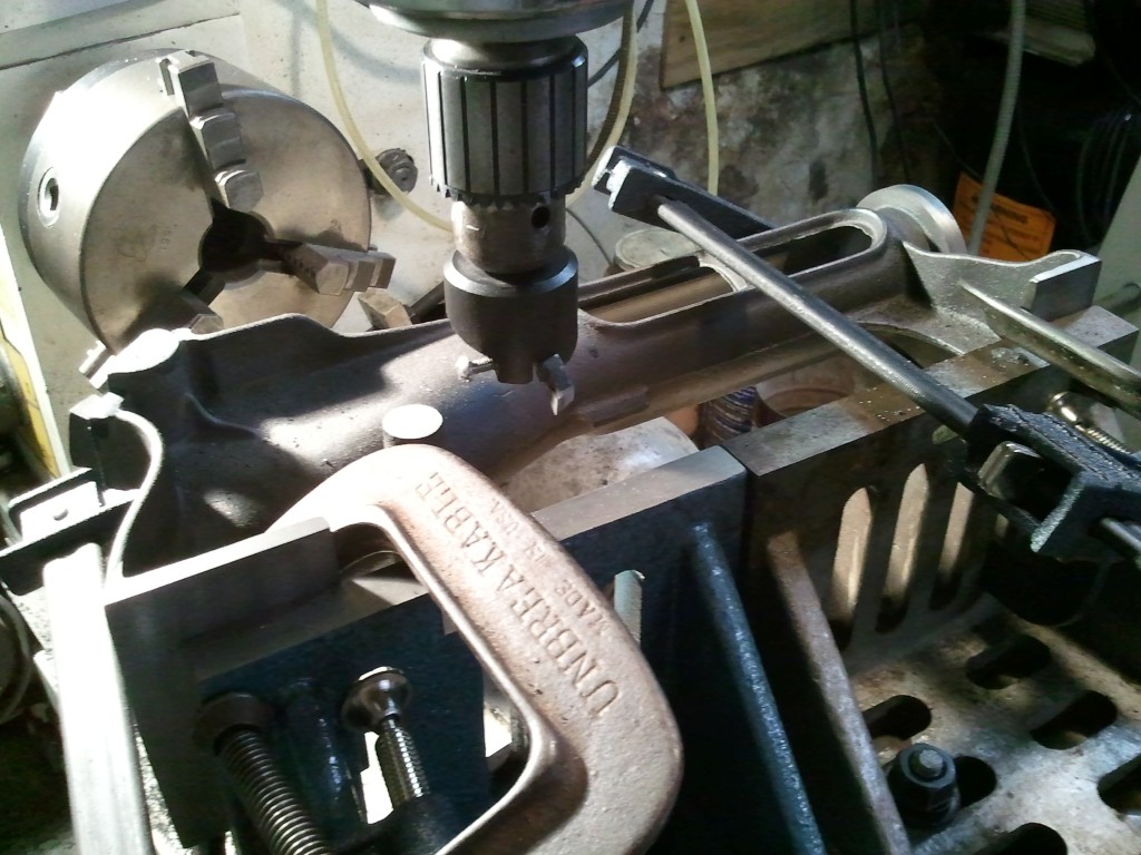
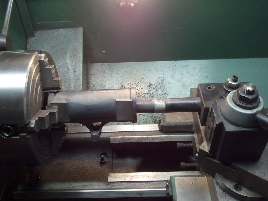
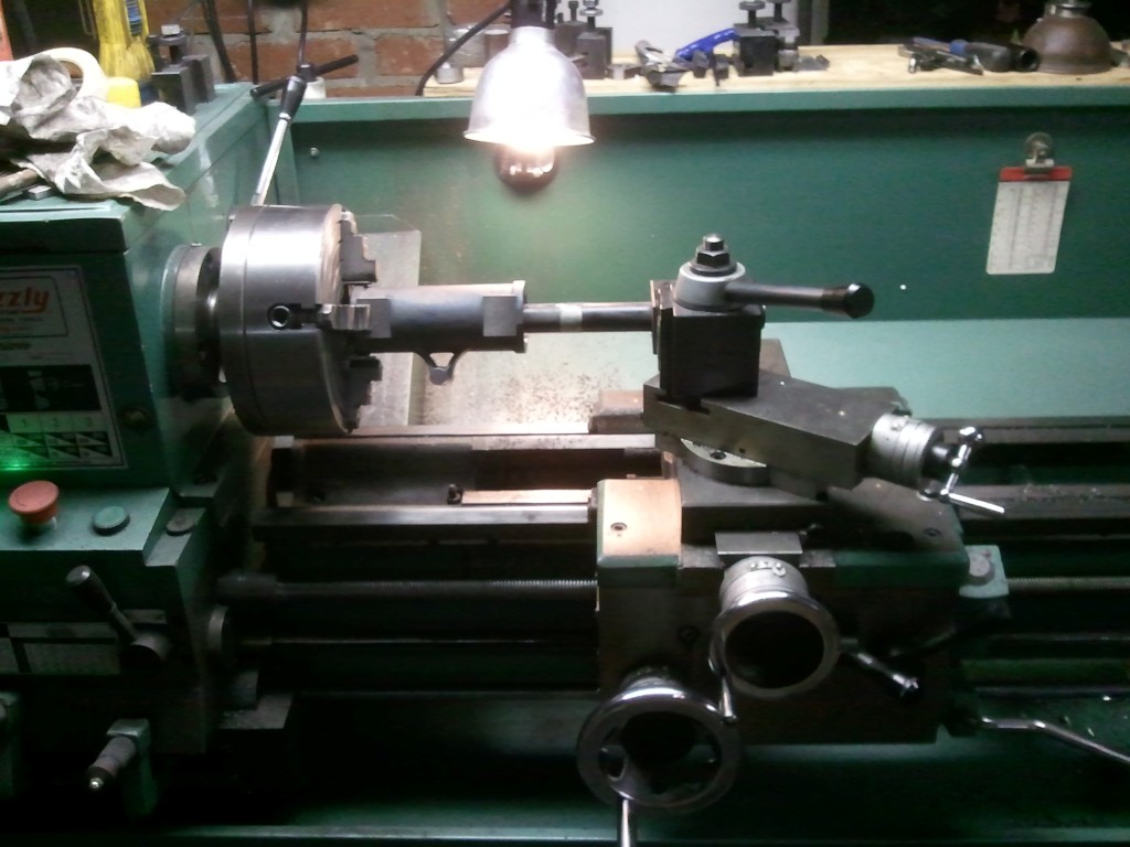
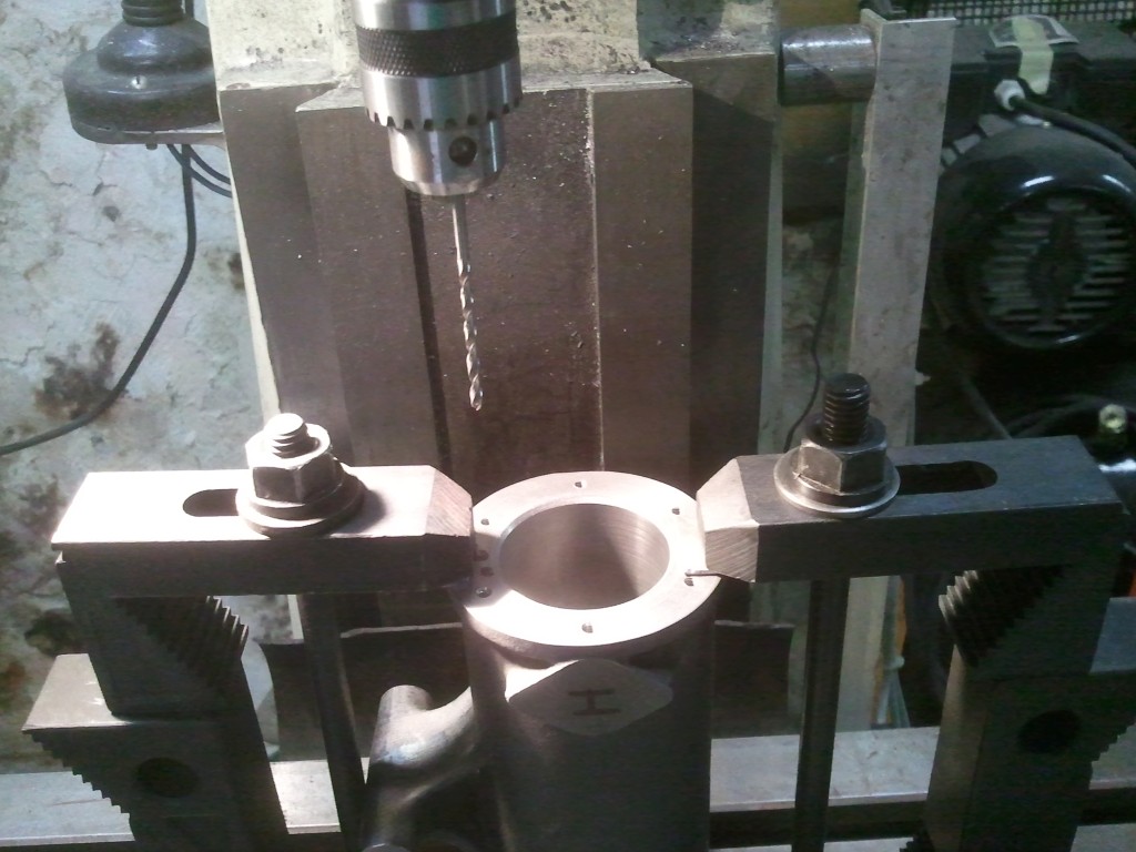
 The
bore liner is in and finished bored, the end holes are drilled and
tapped. Now I can drill the holes for the intake and exhaust.
I located the top of the bar with the height gauge and came down
0.750". The angle plates keep it square with the pads and the bar in
V blocks keep it parallel to the plate. Now I have the Y axis
center line for the holes. I can edge find the front face for
the X axis. Be very careful drilling the countershaft hole.
Make sure your drill is sharp and the point is in the center.
I drilled this from both sides because I didn't want the drill
walking during an almost 3" deep hole.
The
bore liner is in and finished bored, the end holes are drilled and
tapped. Now I can drill the holes for the intake and exhaust.
I located the top of the bar with the height gauge and came down
0.750". The angle plates keep it square with the pads and the bar in
V blocks keep it parallel to the plate. Now I have the Y axis
center line for the holes. I can edge find the front face for
the X axis. Be very careful drilling the countershaft hole.
Make sure your drill is sharp and the point is in the center.
I drilled this from both sides because I didn't want the drill
walking during an almost 3" deep hole.