Mery Explosive Engine - page 2
It occurred to me that to the casual reader, these operations may seem broken or out of order. Sometimes an actual size on one part may have a bearing on another. For example, it's more difficult to bore the cylinder than it is to turn the piston, so by boring the cylinder first, if I'm off a thousandth or so, I can adjust when I turn the piston. It's this thinking ahead that can keep you out of trouble. Sometimes I also just need to put a piece aside and work on something else while I think of how I want to do the next operation.
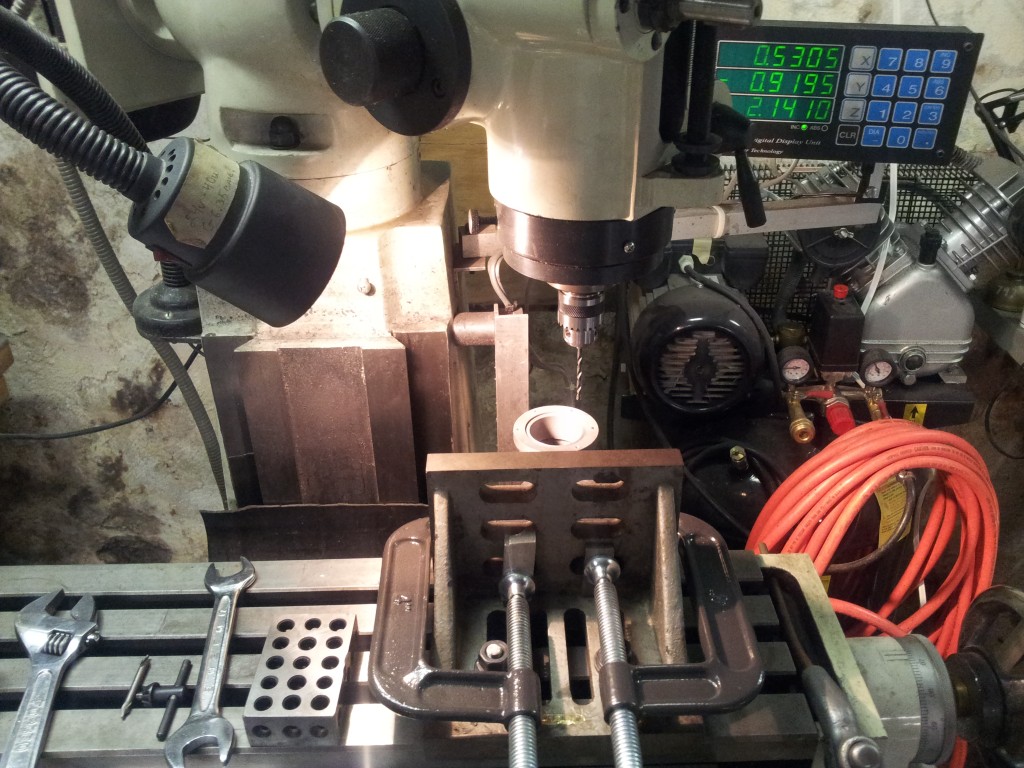 Here is the drilling operation in the base for the cylinder bolt
holes. I hung the base off the back of the table while the
front of the base was clamped to an angle plate. Because of
this, I had to swing the head over to the part.
Here is the drilling operation in the base for the cylinder bolt
holes. I hung the base off the back of the table while the
front of the base was clamped to an angle plate. Because of
this, I had to swing the head over to the part.
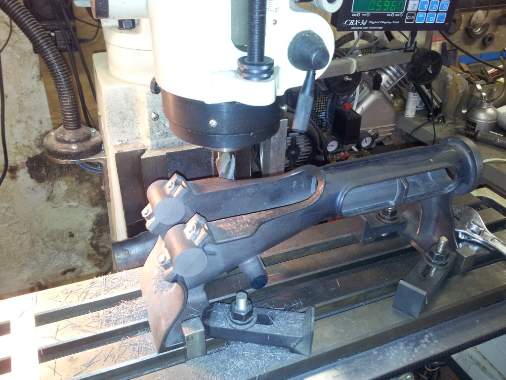 Here
is the setup for cutting the bearing ends. My table travel
wasn't long enough to allow me to edge find the actual bore so I
centered using the scribe line on the back of the part. I
checked how close I was to the bore center afterwards and it was
.003" off center, way close enough. Just
because it might come in handy I took a skim cut on the top face to
level off the sides of the housing. I still have to drill the
holes in the bottom for the base and this gives me something to set
down on. After cleanup and paint it won't show.
Here
is the setup for cutting the bearing ends. My table travel
wasn't long enough to allow me to edge find the actual bore so I
centered using the scribe line on the back of the part. I
checked how close I was to the bore center afterwards and it was
.003" off center, way close enough. Just
because it might come in handy I took a skim cut on the top face to
level off the sides of the housing. I still have to drill the
holes in the bottom for the base and this gives me something to set
down on. After cleanup and paint it won't show.
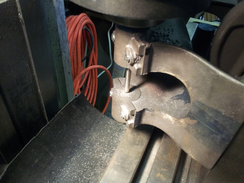
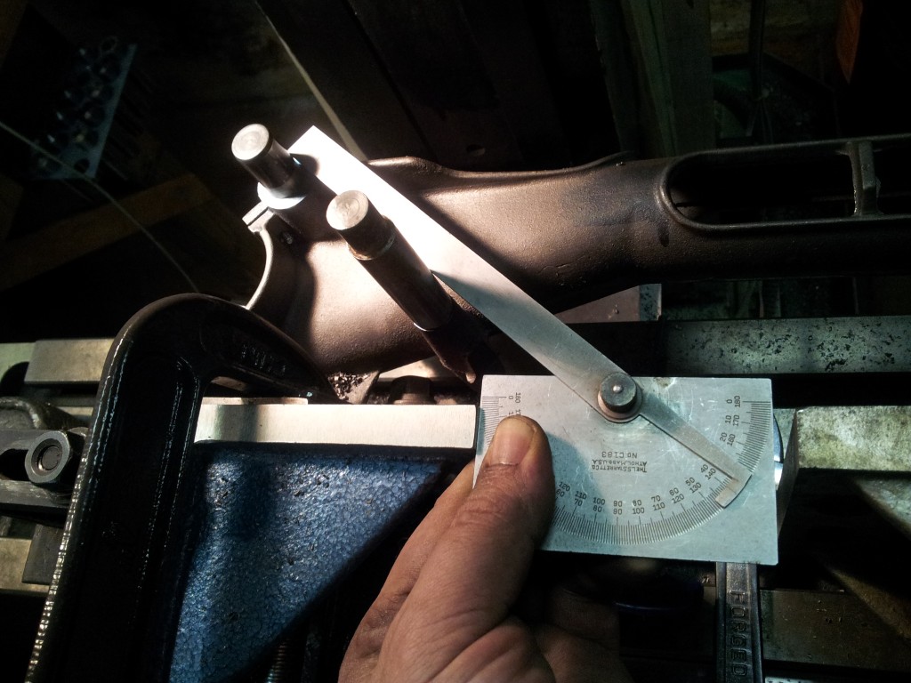
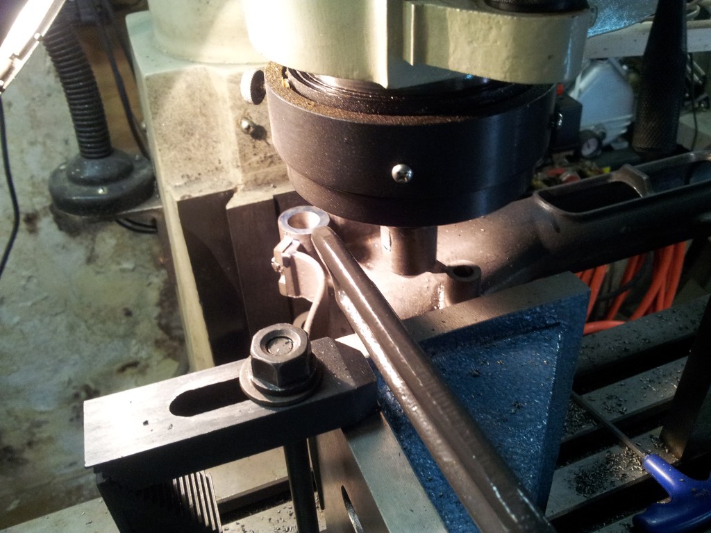 Drilling
and boring for the crankshaft. Rather than drilling the second
crank hole straight through, I used a long center drill to locate it
in case the drill walked. The quill feed was a bit too loose
to bore with so I used table up feed. I also cut the end of
the countershaft section. The countershaft hole has a critical
location of 3.125 from the center of the crankshaft because of the
gear mesh. The other dimensions aren't critical because they involve
the eccentric rods that can have the length adjusted. So to
find the 3.125" I used the protractor to roughly find the angle.
It's about 40deg so getting out the trig book gave me the 'up' and
'over' dimensions for the hole. Then I flipped it over and cut the other
end of the countershaft section.
Drilling
and boring for the crankshaft. Rather than drilling the second
crank hole straight through, I used a long center drill to locate it
in case the drill walked. The quill feed was a bit too loose
to bore with so I used table up feed. I also cut the end of
the countershaft section. The countershaft hole has a critical
location of 3.125 from the center of the crankshaft because of the
gear mesh. The other dimensions aren't critical because they involve
the eccentric rods that can have the length adjusted. So to
find the 3.125" I used the protractor to roughly find the angle.
It's about 40deg so getting out the trig book gave me the 'up' and
'over' dimensions for the hole. Then I flipped it over and cut the other
end of the countershaft section.
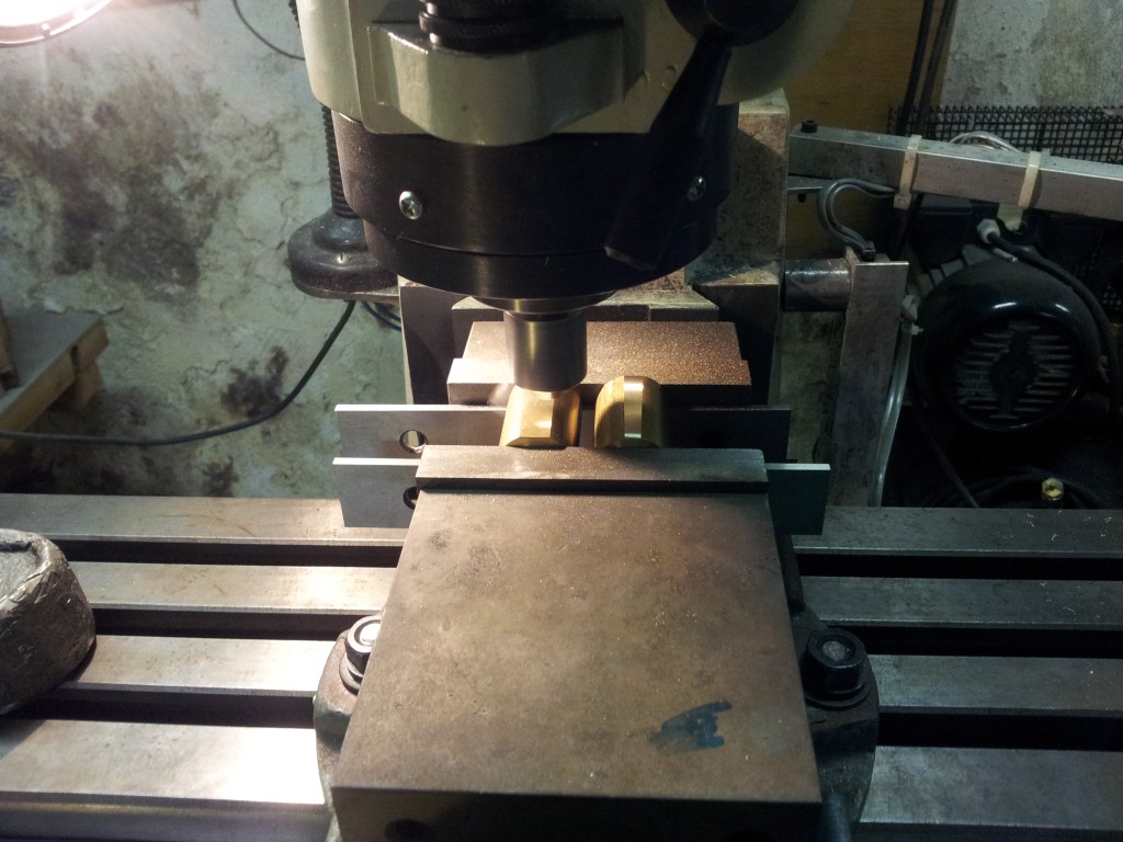 Now
that I have the exact 'as built' diameter of the casting crank bores, I can
make the bearings. A piece of 1" brass cut in half then flats
milled on the back and the mating surfaces milled clean as a pair
puts the split centered on the back flats. Soft solder the
halves together and setup in the 4 jaw indicating on the flats.
Now
that I have the exact 'as built' diameter of the casting crank bores, I can
make the bearings. A piece of 1" brass cut in half then flats
milled on the back and the mating surfaces milled clean as a pair
puts the split centered on the back flats. Soft solder the
halves together and setup in the 4 jaw indicating on the flats.
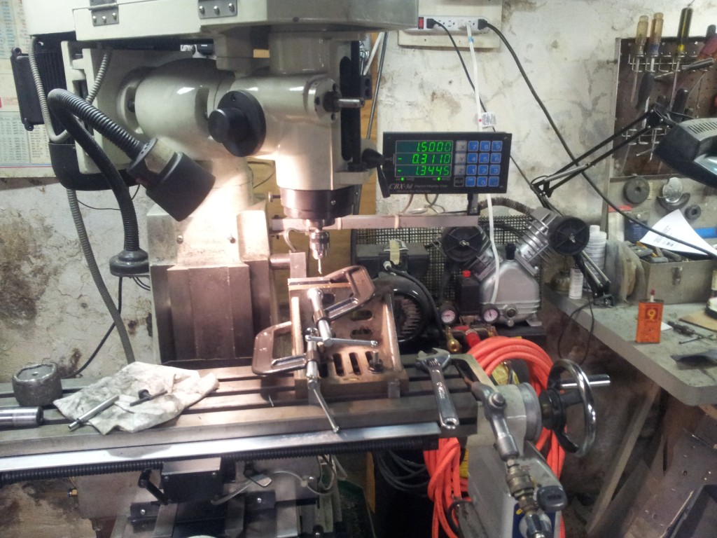
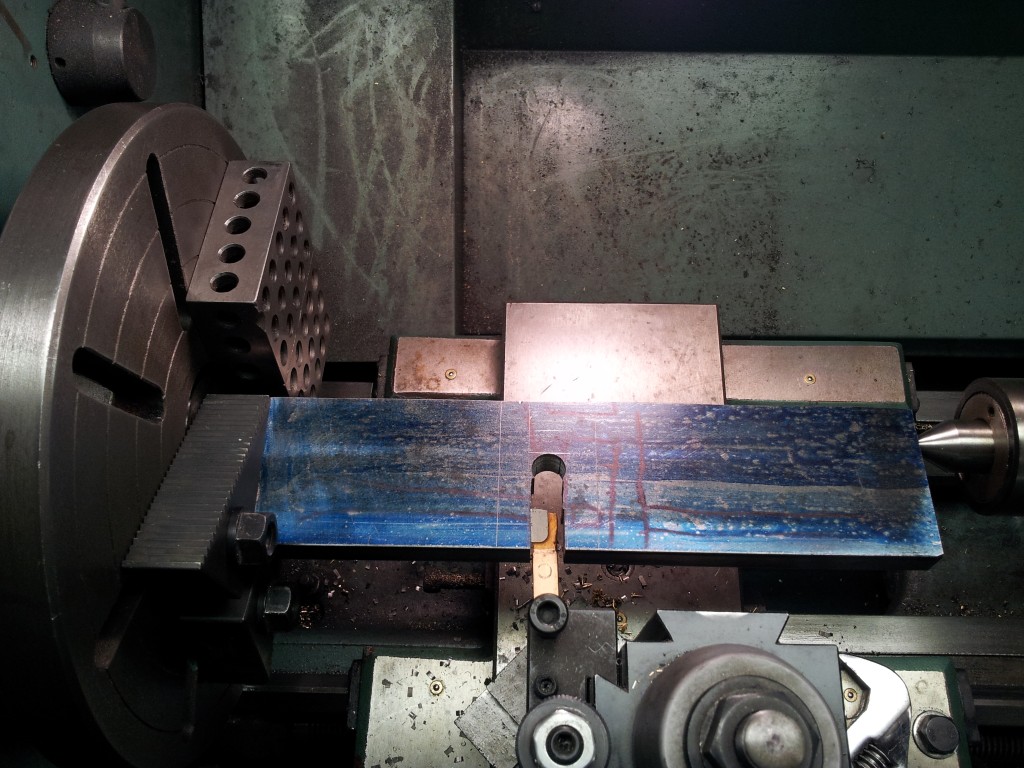
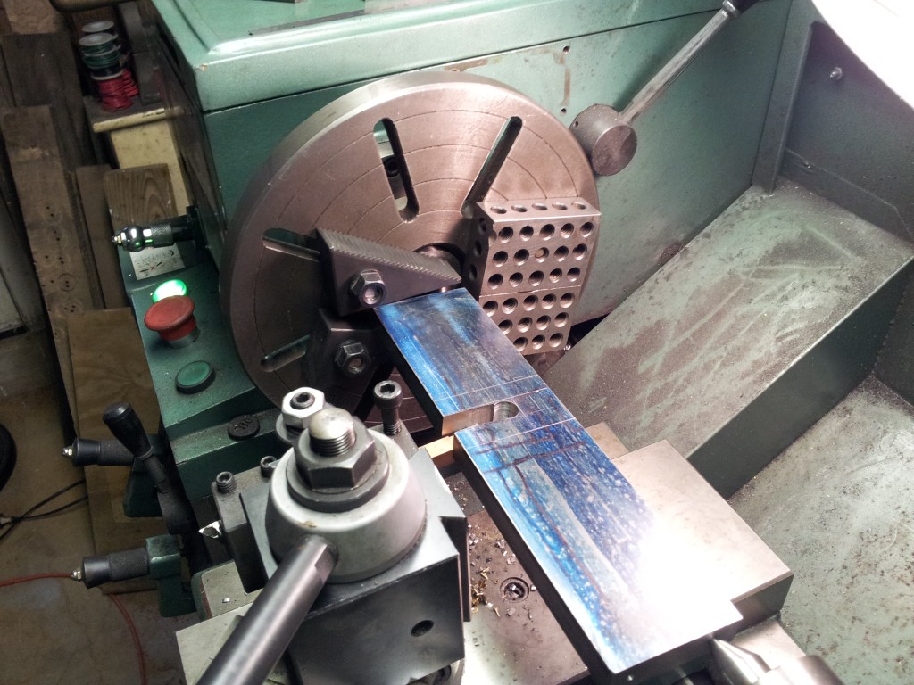
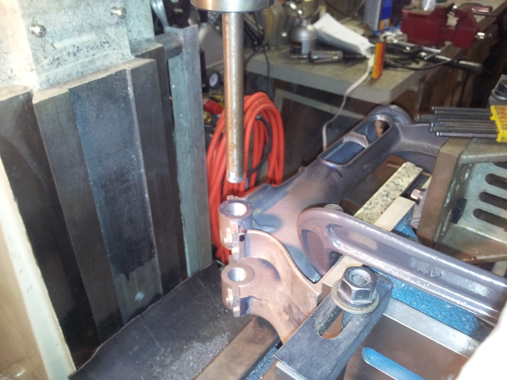
 Now
the fun part. The crank is a piece of 5/8" by 4" CRS. I
laid out the rough lines on it and had to saw it the long side for
width. Then I milled it to length and drilled the ends on
centers for the shaft and the throw. I then drilled a hole and
sawed out the chunk where the throw would be cut. This is
easier than trying to turn it out for hours listening to chunk,
chunk in the lathe. You can't take large cuts in this type of
setup. So now it's on to the lathe. Mounted between
centers, turn the throw first. Little by little until you get
to about .010 all around. I then finished the sides with a
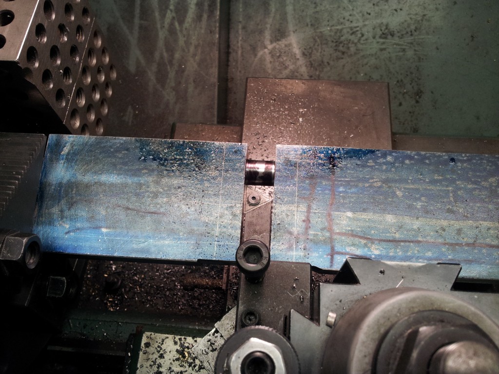
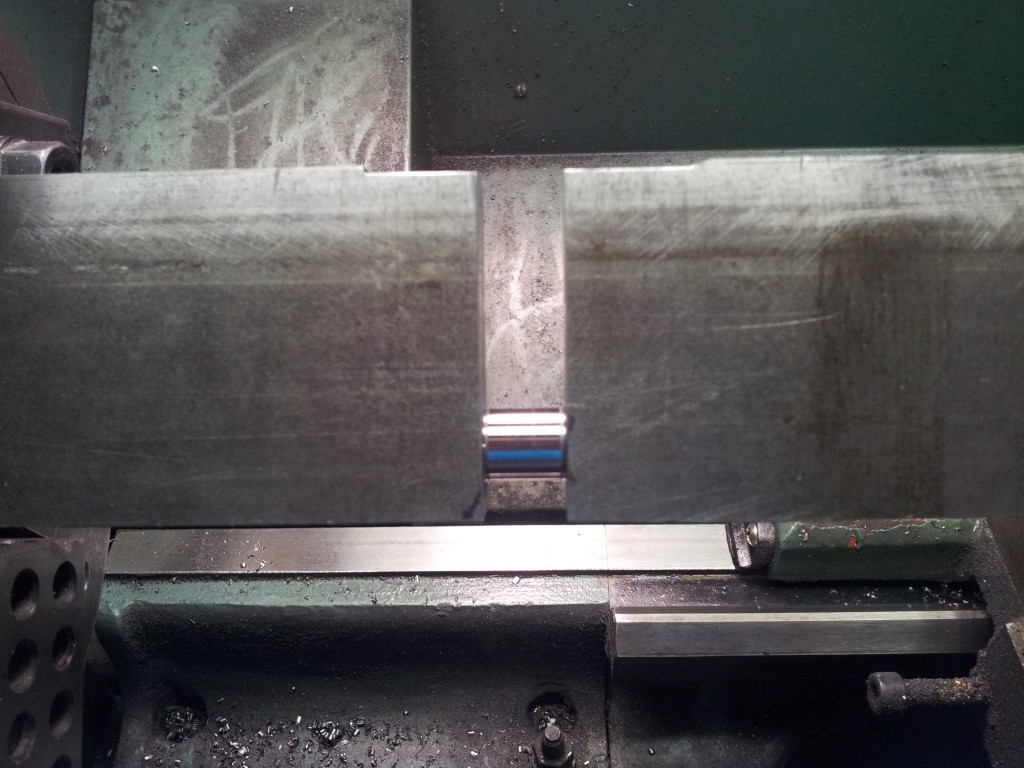
radius nosed tool (pic4). Next I radius ground the 3/32
parting tool and turned the diameter a couple thousandths at a time.
I had very small steps in the corners because of the radius mismatch
but a jewelers file made quick work of that. Then a bit of 320
grit and 400 grit and that part is done. Oh, don't forget
about the back end radius show on the top of the part in pic5.
Notice in pic3 the 1,2,3 blocks looking useless? Can you say
counterbalance? BTW, I only ran this at 220 RPM.
Now
the fun part. The crank is a piece of 5/8" by 4" CRS. I
laid out the rough lines on it and had to saw it the long side for
width. Then I milled it to length and drilled the ends on
centers for the shaft and the throw. I then drilled a hole and
sawed out the chunk where the throw would be cut. This is
easier than trying to turn it out for hours listening to chunk,
chunk in the lathe. You can't take large cuts in this type of
setup. So now it's on to the lathe. Mounted between
centers, turn the throw first. Little by little until you get
to about .010 all around. I then finished the sides with a
radius nosed tool (pic4). Next I radius ground the 3/32
parting tool and turned the diameter a couple thousandths at a time.
I had very small steps in the corners because of the radius mismatch
but a jewelers file made quick work of that. Then a bit of 320
grit and 400 grit and that part is done. Oh, don't forget
about the back end radius show on the top of the part in pic5.
Notice in pic3 the 1,2,3 blocks looking useless? Can you say
counterbalance? BTW, I only ran this at 220 RPM.
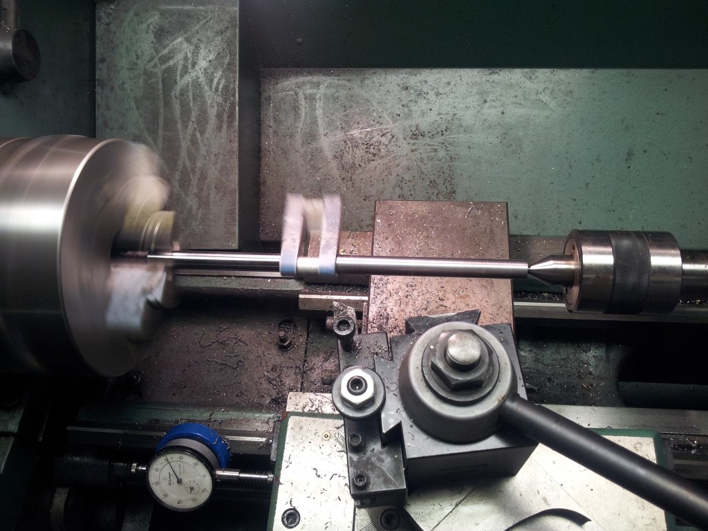 The
above group of pictures is cutting the throw. The first
picture here is after cutting one of the shafts on the band saw and
still turning a rough cut between centers. I left it about
.015" large on both the diameter and the throw side. I didn't
get a shot roughing the other side but it was the same, band saw the
large piece and rough turn to .015" large. I did start turning
finish dimension between centers but toward the center I started to
chatter because of the off balance throw. I was turning at
600RPM. I ended up finishing the crank in a 3 jaw chuck.
By turning the majority between centers, any stress bowing was taken
out but I still chucked it at the end of the shaft instead of
grabbing it right up against the throw. The second shot is
cutting the throw side to finish. Once I had that, I went back
to the shaft to cut the final .005". Finished dimension for
the shafts is .4995". I turned to .501" and used 320 then 400
grit to polish off the last bit to size. Two things to note: I
turned a chunk of aluminum to exactly fill the gap of the throws so
the pressure of the center didn't bend them. It's held in
place with (don't laugh) wood glue. The wood glue sticks
enough to hold it from falling out without the pressure of the
center but cleans up easily and isn't brittle. Also, note the
indicator in the second shot lower left. That's how I repeat
working to a shoulder. You don't need a fancy digital readout
to work accurately.
The
above group of pictures is cutting the throw. The first
picture here is after cutting one of the shafts on the band saw and
still turning a rough cut between centers. I left it about
.015" large on both the diameter and the throw side. I didn't
get a shot roughing the other side but it was the same, band saw the
large piece and rough turn to .015" large. I did start turning
finish dimension between centers but toward the center I started to
chatter because of the off balance throw. I was turning at
600RPM. I ended up finishing the crank in a 3 jaw chuck.
By turning the majority between centers, any stress bowing was taken
out but I still chucked it at the end of the shaft instead of
grabbing it right up against the throw. The second shot is
cutting the throw side to finish. Once I had that, I went back
to the shaft to cut the final .005". Finished dimension for
the shafts is .4995". I turned to .501" and used 320 then 400
grit to polish off the last bit to size. Two things to note: I
turned a chunk of aluminum to exactly fill the gap of the throws so
the pressure of the center didn't bend them. It's held in
place with (don't laugh) wood glue. The wood glue sticks
enough to hold it from falling out without the pressure of the
center but cleans up easily and isn't brittle. Also, note the
indicator in the second shot lower left. That's how I repeat
working to a shoulder. You don't need a fancy digital readout
to work accurately.
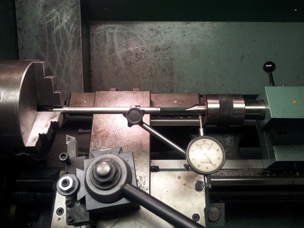 Once
I started to get close to final diameter I noticed I was turning a
taper of about .001". I could live with it and compensate for
it with emery paper later or I could fix it. Sometimes people
over think resetting the tailstock. In my case that was the
cause of the taper, it was off center. I took the indicator
off the mag base and chucked it. Now by spinning it around the
center I was able to indicate in the center so I had about a .0002
taper. I think I'll start another section on hints and tips
for this kind of thing to help others that are just starting.
Once
I started to get close to final diameter I noticed I was turning a
taper of about .001". I could live with it and compensate for
it with emery paper later or I could fix it. Sometimes people
over think resetting the tailstock. In my case that was the
cause of the taper, it was off center. I took the indicator
off the mag base and chucked it. Now by spinning it around the
center I was able to indicate in the center so I had about a .0002
taper. I think I'll start another section on hints and tips
for this kind of thing to help others that are just starting.
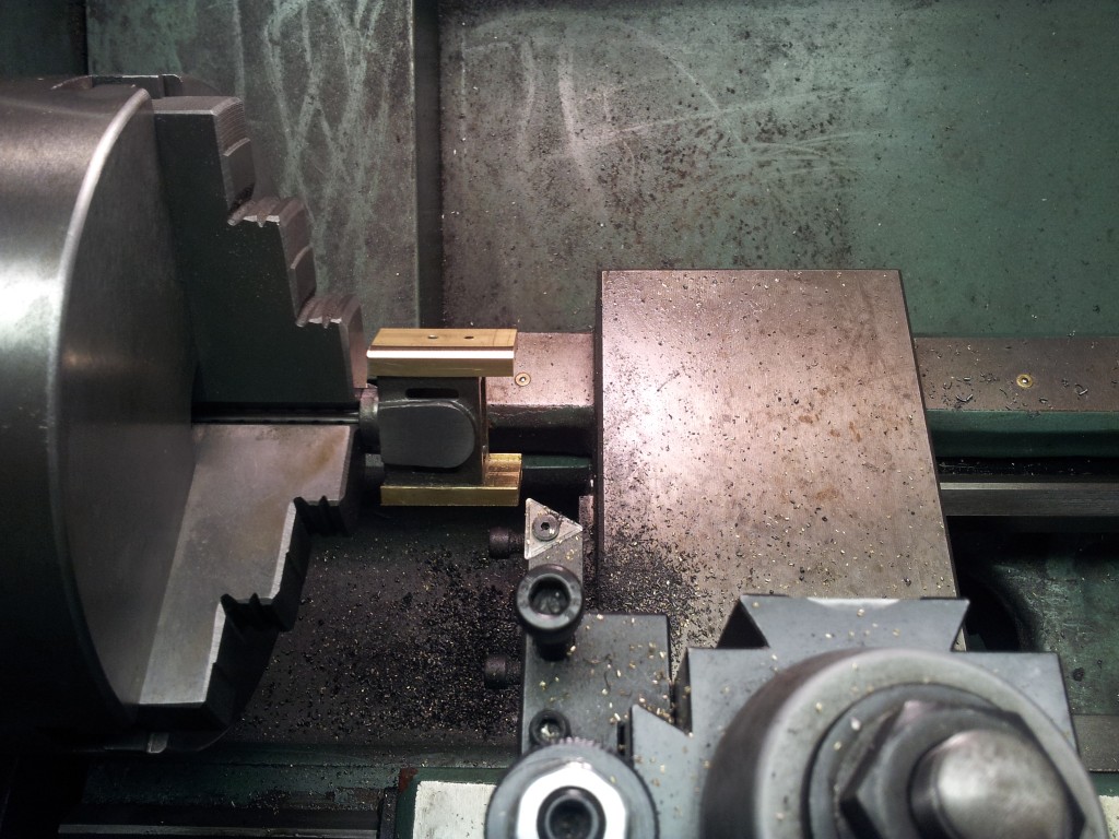 I
had 2 options for making the crosshead shoes; I could turn a round
piece to 1.500" and cut out the shoe parts then mill the back of a
semi round part OR mill the shoes out of bar stock and bolt them to
the crosshead and turn them. By doing the later, it's much
quicker, more accurate and it's concentric to the 1/4-28 thread.
They are only held on by one 4-40 stud so I cheated a bit and added
a drop of epoxy when I bolted them to keep them from moving while I
turned them. Next, I drilled the tapered pin hole. I
reamed it with the taper pin reamer but only to the point of getting
the taper in both sides. I didn't ream to depth. It's
easier to finish the depth when the pin is done. The reamer is
fine tuning.
I
had 2 options for making the crosshead shoes; I could turn a round
piece to 1.500" and cut out the shoe parts then mill the back of a
semi round part OR mill the shoes out of bar stock and bolt them to
the crosshead and turn them. By doing the later, it's much
quicker, more accurate and it's concentric to the 1/4-28 thread.
They are only held on by one 4-40 stud so I cheated a bit and added
a drop of epoxy when I bolted them to keep them from moving while I
turned them. Next, I drilled the tapered pin hole. I
reamed it with the taper pin reamer but only to the point of getting
the taper in both sides. I didn't ream to depth. It's
easier to finish the depth when the pin is done. The reamer is
fine tuning.
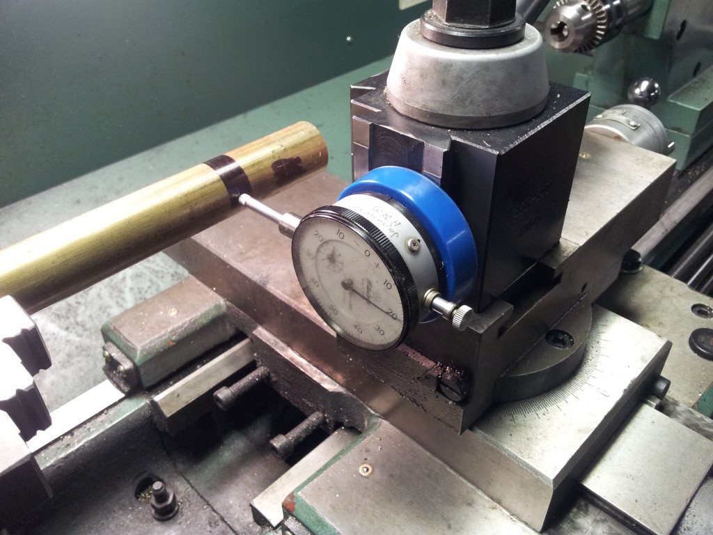
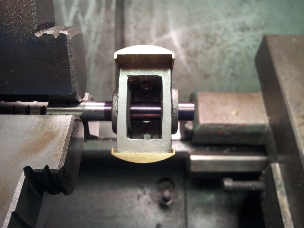
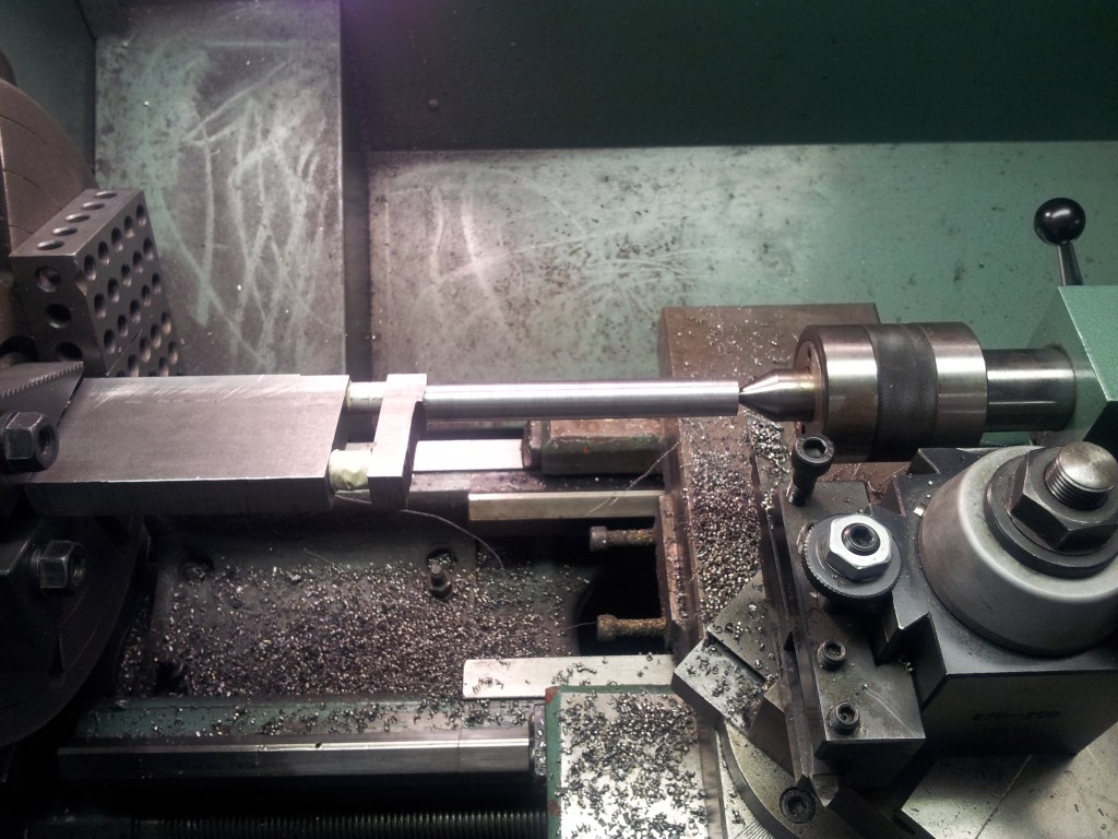
 The
crosshead pin needs two sections tapered and a section in the middle
straight. Oh, and a threaded section... Take it one step
at a time. Before you do anything, set the taper. Taper
pins are tapered .250" per foot. That comes out to .0208"per
inch. PIC-1 is a straight shaft with marks at one and two
inches. I swiveled the cross slide to 1deg and started there.
You want the indicator to show 1/2 of the .0208" or .0104" per inch.
The longer you can indicate, the closer you can get to correct.
I eventually went to 3". That's .0312" for the whole 3".
Try for less than .0005" error. Now turn the straight section
first. Add up the threaded section, the small tapered section,
and the threaded section and that's the length of the .281" to turn.
Now turn the threaded section and thread. Now for the taper.
Start cutting that, your goal is to have the tapered sections .187"
wide, that's all. Don't worry about diameters, the finish ream
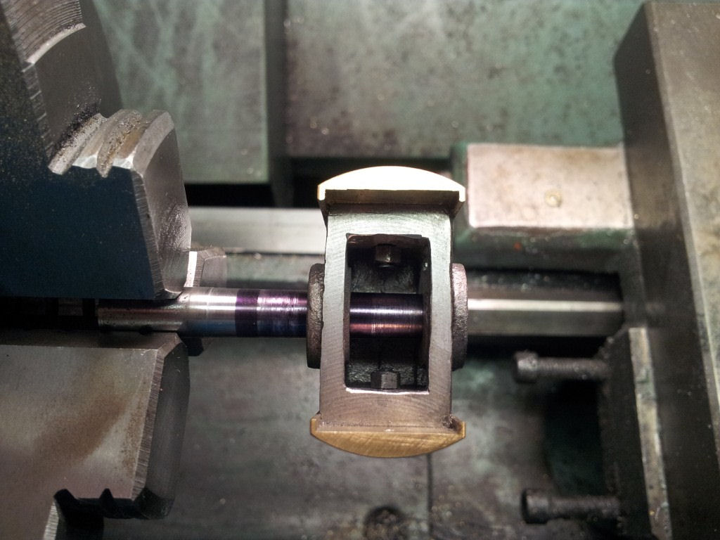
by hand will walk that right in for you. In the second and
third pics are the crosshead pushed on the taper lightly with marker
ink on the shaft. The third pic is the crosshead pulled off a
bit showing the taper contact on both sections. If you're not
sure of your taper, turn a practice piece. The better your
taper, the less chance of that pin coming loose later. Don't
be afraid of using a bit of 320 grit to help the fit.
The
crosshead pin needs two sections tapered and a section in the middle
straight. Oh, and a threaded section... Take it one step
at a time. Before you do anything, set the taper. Taper
pins are tapered .250" per foot. That comes out to .0208"per
inch. PIC-1 is a straight shaft with marks at one and two
inches. I swiveled the cross slide to 1deg and started there.
You want the indicator to show 1/2 of the .0208" or .0104" per inch.
The longer you can indicate, the closer you can get to correct.
I eventually went to 3". That's .0312" for the whole 3".
Try for less than .0005" error. Now turn the straight section
first. Add up the threaded section, the small tapered section,
and the threaded section and that's the length of the .281" to turn.
Now turn the threaded section and thread. Now for the taper.
Start cutting that, your goal is to have the tapered sections .187"
wide, that's all. Don't worry about diameters, the finish ream
by hand will walk that right in for you. In the second and
third pics are the crosshead pushed on the taper lightly with marker
ink on the shaft. The third pic is the crosshead pulled off a
bit showing the taper contact on both sections. If you're not
sure of your taper, turn a practice piece. The better your
taper, the less chance of that pin coming loose later. Don't
be afraid of using a bit of 320 grit to help the fit.
Copyright © 2011
Phil Leinhauser
Template Design:
Expression Web Tutorials & Templates